

Article reprinted from MAN (Modern Application News)
Article reprinted from CTE – Simultaneous Savings
Article reprinted from CTE July 2012 – Cutting Downtime
Article reprinted from CTE Aug 2012 – New Life For Old Iron
CNC Flute Grinder Has The Power to Replace Aging Mechanical Grinders
FLEXIBLE CNC GRINDER BRINGS PRECISION PARTS INTO SHARPER FOCUS
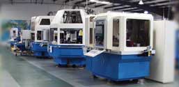
ITM Universal Grinders

Tooling and cutter manufacturers realize that having flexibility in a single grinding machine is important, but not at the expense of sacrificing efficiency.
Making accurate cutters and precise tooling on a universal CNC (computer numerical control) grinder requires a single machine capable of producing workpieces of varying sizes and geometry. To achieve this, the grinder must be able to place several different wheels in the grinding position, ensuring that the most appropriate wheel is available for each operation. The challenge is to design a machine that can handle multiple grinding wheels without compromising accuracy or efficiency. Most grinders of this type have attempted to meet this challenge by using wheel packs or indexing wheel heads.
 Wheel packs consist of multiple grinding wheels stacked on a single flange that is mounted to a spindle. The wheels must be spaced precisely to avoid collisions when using them for the various grinding operations. Larger wheels require more space between each one to keep them from colliding, especially when grinding spiral fluted tools. One way of doing this is to use smaller grinding wheels (50 mm to 100 mm). When a smaller wheel is used in an operation that would be better suited for a larger wheel, machine efficiency is compromised.
Indexing wheelheads consist of multiple grinding spindles, each one capable of accepting a single wheel or a wheel pack. Two opposing spindles are placed horizontally, on centerline, in a wheelhead. A pivot point in the center of the wheelhead, between the drive ends of the opposing spindles, establishes a rotary axis for indexing either spindle into the grinding position. This places the pivot point relatively far away from the grinding wheel, limiting the positioning accuracy of the wheelbead and compromising the accuracy of the machine. Automatic wheel changers also face the problem of limited positioning accuracy. In addition, the time it takes to index a spindle or a wheel changer is time that is added to the total machine cycle.
Using Rigidity to Improve Flexibility
International Tool Machines (ITM) designed their Series Universal Grinders to be flexible with-out the compromises inherent in wheel packs or indexing wheelheads. “Our machine designs have always incorporated a heavy stress-relieved base to provide rigidity and dampening,” says ITM president (retired), “but it occurred to us that we were not using that rigidity to its fullest potential.” ITM’s engineers redesigned the Series Universal Grinders by turning the design on end, mounting up to three grinding spindles vertically in the machine base. This approach maximizes support and rigidity for the grinding spindles while enabling the machine to take heavier cuts when needed. Having three spindles ensures that the most appropriate wheel is available for each grinding. While wheel packs can be used in applications where they will not create interference problems, they are not absolutely necessary. The additional rigidity provided for the spindle enables the machine to operate with conventional, CBN (cubic boron nitride) or diamond wheels.
According to ITM’s President, additional benefits were determined as the design progressed. More room behind the grinding wheels provides the space for a table-mounted CNC dresser that can be used to dress any type of grinding wheel, including diamond. “Arranging the tool infeed axis vertically, rather than horizontally as in our Series Gear Grinder machines, allows us to use gravity to our advantage to eliminate backlash,” he says. After settling the flexibility issue, ITM focused on making the machine more productive. The Series Heavy Duty 5-Axis Grinder End Grinder is equipped with a fully automatic cassette loader and features an adjustable 16 mm chuck. Combined with the ability to dress any wheel type in the machine, this enables the grinder to operate uninterrupted for long periods of time. Menu-driven control screens enable the control to save all tool and wheel data for rapid recall for future production runs. The PC control for the Series End Grinder includes a PentiumTM processor, a 3 GB hard disk, 32 MB EDO RAM, a CD ROM and a USB. The PC enables users to run “open system’ CNC and third-party software.
ITM President notes that operators will now be able to run PC-based programs at the machine, enabling them to generate original NC programs and to verify grinding results visually on-screen before grinding parts. He also points out that the modem will allow operators to communicate directly with ITM through the Internet to send and receive messages, program updates and troubleshooting tips.
“When we first started working on this machine we didn’t want to limit ourselves,” says ITM’s President. “We just set out to design a machine that would take advantage of the latest technology available for software, controls and components. This would allow users to operate the machine 24 hours a day, seven days a week, with minimal attendance. With the end goal clearly defined, the design of the machine developed logically. That’s how we came up with the name, ’20-20.’ Every aspect of the design came into sharper focus as the project progressed and the final image was clearly in front of us.”
Wheel packs consist of multiple grinding wheels stacked on a single flange that is mounted to a spindle. The wheels must be spaced precisely to avoid collisions when using them for the various grinding operations. Larger wheels require more space between each one to keep them from colliding, especially when grinding spiral fluted tools. One way of doing this is to use smaller grinding wheels (50 mm to 100 mm). When a smaller wheel is used in an operation that would be better suited for a larger wheel, machine efficiency is compromised.
Indexing wheelheads consist of multiple grinding spindles, each one capable of accepting a single wheel or a wheel pack. Two opposing spindles are placed horizontally, on centerline, in a wheelhead. A pivot point in the center of the wheelhead, between the drive ends of the opposing spindles, establishes a rotary axis for indexing either spindle into the grinding position. This places the pivot point relatively far away from the grinding wheel, limiting the positioning accuracy of the wheelbead and compromising the accuracy of the machine. Automatic wheel changers also face the problem of limited positioning accuracy. In addition, the time it takes to index a spindle or a wheel changer is time that is added to the total machine cycle.


